
Finally I received everything and soldering could start. Being a novice never soldered PCB, I was kind of worried about how this would enfold, especially when looking at the smallest pieces and not being familiar with schematics. But to my surprise things wasn’t  as hard as I thought it would be. The tiniest bits actually was not the issue at all, but the larger screen connector on the other hand caused me some headache. The thing is that with some preparations and practice, the proper technique is really not that hard to master. YouTube is a must and I found among others this video very helpful. The right tools is definitely also crucial and my soldering station described in earlier posts surely made the work manageable. The hot
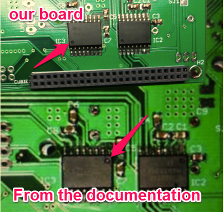 air gun saved my @ss on several occasions when rework was needed on the bigger parts with multiple pins (Had to change polarity to IC2 and IC3) . Well back to the screen connector, the pins are extremely small with very little spacing. The first attempt was a complete failure, with bridges, broken leads on the board and slightly off correct position. These problems was not clearly visible trough normal inspection, but it revealed it self when the first test with power connected. The 5 to 3.3 volt regulator (IC1) did not give output and went into thermal protection. After testing for continuity, reading schematics and removing items in reversed order, I was finally left with
  the LCD connector. It was removed, and surly the board loaded and all 5v and 3.3v checkpoints passed the test. Luckily We had one connector in spare, so after careful positioning it with just a tiny amount of solder on each end pad, pins was soldered with the smallest amount of solder possible. Even then the continuity test failed 3 times either because of bridges or not contact on one or more pins. Adding more solder to gain contact, easily made another bridge in result. After some rework with solder wick all tests were passed, and it was time to connect the LCD screen. Success!! The screen lit up and after loading the software XCsoar surely came to live. A little trial and error to
 figure out the correct jumper settings, but now everything looks good.
Next up is the sensor board on my part.
The following two images show the key components for this Project, first one is the Cubieboard2 which is purchased as shown.  Uses Linux as platform. To interface the Cubieboard2 with the screen, touchscreen, sensorboard and RJ45 connectorboard an Adapterboard is required. (Green Board). This house the respective connections and
  DC/DC converter needed to operate the system.
THE HOUSING
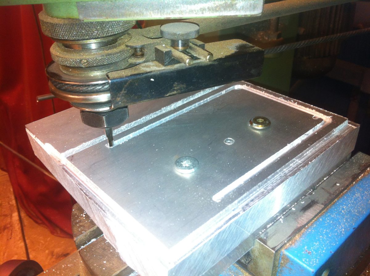 My partner in crime on this project – Haldor, is busy making the housing out of aluminum sheets the good old fashion way. Based on the descriptions and his good craftsmanship, I’m confident the electronics will be well taken care of once it is installed in our LS6.

A 25mm thick aluminum billet is used to mill the front frame for the Flight Computer. An old-school 3-axis milling machine at work to the rescue! The front side of the panel is completed and now we will mill from the rear side to open up the actual frame for the screen to rest in.
Thank you to everybody on forum.xcsoar.org for assistance and guidance. Also found this blog http://www.eehmke.de/ very helpful as an addition to the documents from the OV project page. Keep ut the good work!
To be continued 🙂